Final Inspection of the
Electrical Installation at
Office Building and Computer Centre, Paro
NIE Paro / Samtse Expansion (BH 22), Bhutan
4. – 18.12.2005

Hans Steiner
Heidenerstrasse 16, CH-9400 Rorschach, T.+ Fax: ++41 +71 855 89 19c/o: Technische Betriebe, Promenadenstrasse 74
Postfach, CH-9401 Rorschach
Telefon ++41 +71 844 22 22, Fax ++41 +71 844 22 33
e-Mail: [email protected]
![]() Schweizer Gesellschaft für internationale Zusammenarbeit
Schweizer Gesellschaft für internationale Zusammenarbeit
St. Moritzstrasse 15, Postfach 181, CH-8042 Zürich
Telefon ++41 +1 368 65 00, Fax ++41 +1 368 65 80
http://www.helvetas.ch; e-mail: [email protected]
Contents
1 Terms of Reference
*2 Program
*2.1 Support from Switzerland
*2.2 Final Inspection at Bhutan
*3 Summary
*4 Distribution System
*4.1 Description
*4.2 Transformer Station
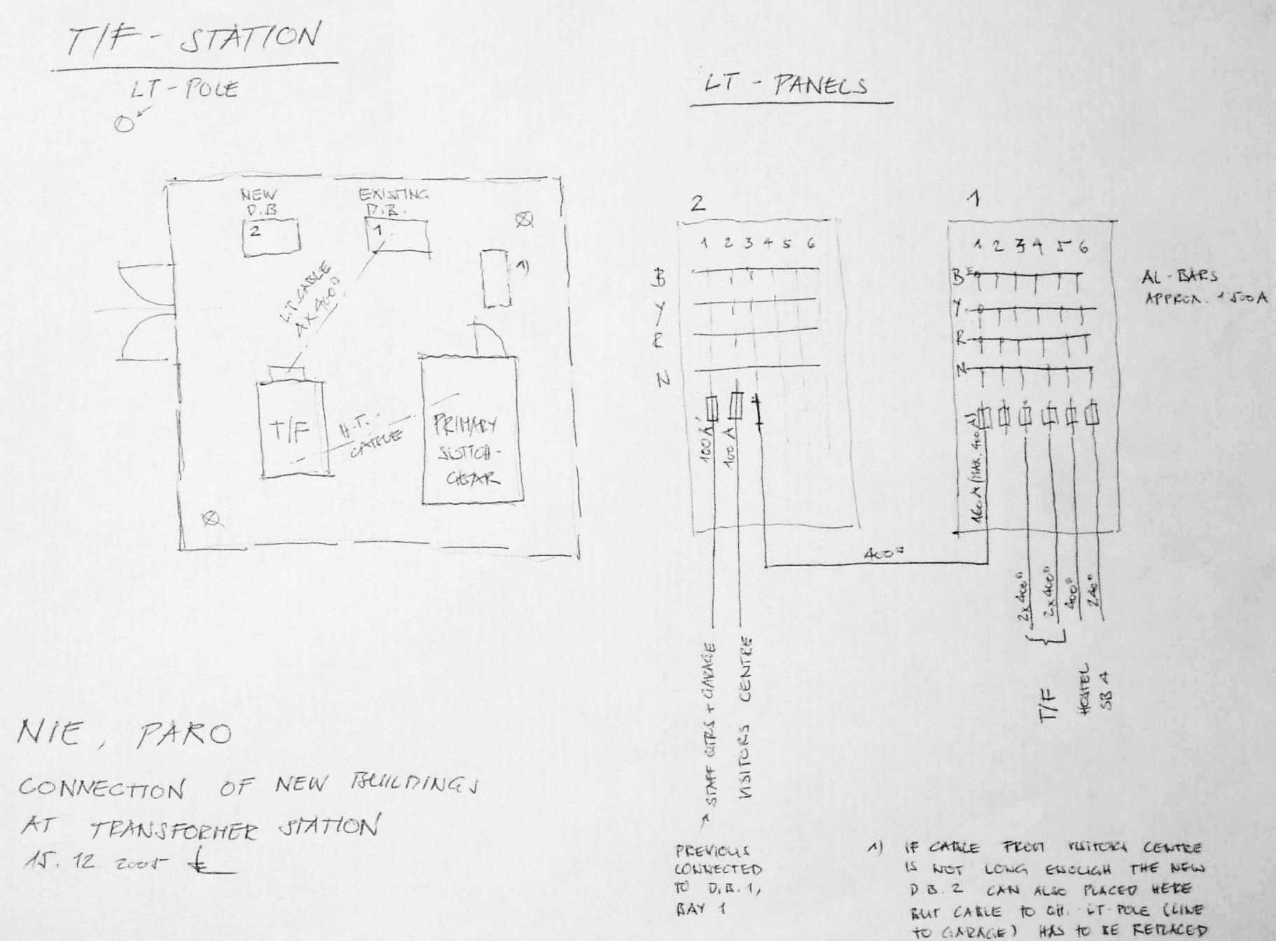
*4.3 Connection of New Buildings to the Transformer Station
*4.4 Main Distribution Panel (MDP 2)
*4.5 Sub-Main Distribution Panels and Sub Distribution Panels
*5 Load Calculation
*5.1 Load Measurement
*5.2 Future Extension
*6 Heating System
*6.1 Connection
*6.2 Thermostat
*6.3 Time Switch
*7 Maintenance
*7.1 Maintenance Unit (or "Gender Balance")
*7.2 Old Kitchen
*7.3 New Kitchen
*7.4 Outdoor Illumination
*8 Safety
*8.1 Measures Against Accidental Contact
*8.2 At the Site
*8.3 Safety by Bhutan Power Corporation Ltd.
*9 Earthing-System
*10 Water Pump
*10.1 Survey
*10.2 Replacement or Extension
*11 Diesel Generator Set
*12 IT network Installation
*13 Rules and Regulations
*14 Measuring Instruments and Testers
*15 Extension Auditorium and Gym-Hall
*16 Extension at Rinpung
*17 Appendix
*17.1 Action Plan
*17.2 Calculation and Billing of the Energy Consumption of the Staff Quarters
*17.3 Connection / Diagram of Thermostat
*17.4 Calculation-of Illumination
*17.5 Documentation of earlier Supports
*
NIE Paro / Samtse Expansion (BH 22)
Consultancy Electrical Expertise by Hans Steiner (HS)
Introduction
Mr Hans Steiner (electrical engineer) provides technical expertise to the design and execution of the electrical installation NIE Paro / Samtse Expansion project. Most of the work is executed in Switzerland in close collaboration with our project architect based in Thimphu. For the final inspection of the electrical installation office building and computer centre a project visit by Mr Hans Steiner is required. (See also Project Document).
Objectives
To inspect the electrical installation of the office building and computer centre executed and provide input to the electrical design of the computer centre Samtse, auditorium and gymnasium Paro. The work is executed in close collaboration with the project team and maintenance unit NIE based at Paro and the project architect in Thimphu.
Time
The work in Paro shall start on the 5.12.2005 and be completed by the 16.12.2005
|
10.10.02 |
Discussion with W. Christen about consultancy job |
free |
|
14.10.02 |
working out time schedule |
free |
|
24.10.02 |
finalise the consulting contract |
free |
|
13.12.02 |
testing teamwork with AutoCAD |
free |
|
03.02.03 |
information for IT cable system |
free |
|
March 2003 |
developing calculation-sheet for heating according to standard SIA 384/2 |
free |
|
21.01.04 |
Meeting with F. Baumgartner, W. Christen |
free |
|
Thu14.04.05 |
Meeting FB at TBR, support |
8 hrs |
|
Tue 10.05.05 |
Support for outdoor illumination |
4 hrs |
|
Fri 24.06.05 |
Load calculation |
2 hrs |
|
Wed 10.08.05 |
printing and saving mails and drawing files |
free |
|
Fri 26.08.05 |
checking layouts |
3 hrs |
|
Tue 30.08.05 |
Load calculation |
free |
|
Thu 08.09.05 |
checking of panels |
2 hrs |
|
Fri 09.09.05 |
correction of panels |
4 hrs |
|
Mon 12.09.09 |
dimensioning heating controls |
free |
|
Tue 13.09.05 |
support for heating controls, contactors |
3 hrs |
|
Tue 20.09.05 |
checking of panels |
2 hrs |
|
Wed 21.09.05 |
correction of panels |
4 hrs |
|
Tue 27.09.05 |
checking and corrections of panels |
4 hrs |
|
Thu 29.09.05 |
checking and corrections of panels |
4 hrs |
|
Fri 30.09.05 |
Load calculation |
free |
|
Wed 12.10.05 |
checking and corrections of panels |
4 hrs |
|
Thu 13.10.05 |
support on heating ctrls, load calculation |
8 hrs |
|
Fri 14.10.05 |
load calculation |
free |
|
Tue 18.10.05 |
support on main supply cable |
4 hrs |
|
Thu 20.10.05 |
printing mails and drawings |
free |
|
Fri 18.11.05 |
preparation |
free |
|
Wed 23.11.05 |
preparation |
4 hrs |
|
Fri 02.12.05 |
preparation |
free |
|
Sat 03.12.05 |
Preparation in CH |
1 |
|
Sun 04.12.05 |
Flight to Delhi |
1 |
|
Mon 05.12.05 |
Flight to Paro; visit at site office; first visual checks at the site |
1 |
|
Tue 06.12.05 |
Meeting Chimi, Principal; check of the water pump, checking installation at Rinpung |
1 |
|
Wed 07.12.05 |
drive to Thimphu, work on tender doc. at office FB (illumination, distribution panels) |
1 |
|
Thu 08.12.05 |
work at office FB (emergency illumination, panels); visit Mr. Wangdi, City Corporation |
1 |
|
Fri 09.12.05 |
work at office FB, distribution concept for Rinpung, drive back to Paro |
1 |
|
Sat 10.12.05 |
Weekend (at office from 9 to 12) |
|
|
Sun 11.12.05 |
Weekend |
|
|
Mon 12.12.05 |
preparations for measuring, check of MDP, SDP, heater and controls |
1 |
|
Tue 13.12.05 |
checking panels, measuring of isolation (wiring) |
1 |
|
Wed 14.12.05 |
load estimate, dismantling water pump |
1 |
|
Thu 15.12.05 |
comments diesel gen. set, switching on |
1 |
|
Fri 16.12.05 |
discussion Chimi, work at heating controls |
1 |
|
Sat 17.12.05 |
reporting to WCH, FB; handing over ceremony |
0.5 |
|
Sun 18.12.05 |
Flight to Delhi |
1 |
|
Mon 19.12.05 |
Flight to Zurich |
0.5 |
|
Tue 20.12.05 |
Writing report |
1 |
This report describes mainly my activities during my stay at Bhutan. But it is also a compilation of all my diagrams, tables, calculation tools or sketches I used to illustrate something. All these topics already have been discussed with the parties concerned at the site or at the office. My assistance to this project phase started already in 2002. The collaboration was carried out with e-mail communication while sending questions / explanations as well as whole layouts and diagrams with corrections forth and back. Some information of this collaboration are also included in this report. I tried to compile a "reference book" which documents the situation and serves for the future extension work.
In general it can be said that the realisation of the distribution system, the panels and the installation are much better than in earlier phases. Compared to the last time, actually no shortcomings were found and not many changes had to be made. So by this reason, the action plan becomes very short. For sure this is the result of the yearlong influence and good collaboration already in the planing phase. Meanwhile the electrical layouts and particularly the diagrams of the panels are drawn in clear details, so it is to understand also for the contractors and their labour.
With new technologies like permanent installed heaters and their controls they have still problems and so they did not start at all with this part unless they got advise from the expert on the spot. This makes it very difficult to finish the work and to do a final check of these parts during my stay. With little more initiative like for instance unpacking the material and making a pilot installation, simply to be curious, could lead to a learning effect. Sometimes it is also an advantage that progress is not that high. At the very first day of my stay I could avoid a modification at the panels. Because of difficulties fixing the larger equipment inside the panels they changed to fix it with the help of a wooden board inside the panel. This shows to me, that the background of the standard we try to maintain is not really known. In this case we order difficult to produce and expensive steel panels to reduce the risk of fire. Bringing wood into the panels is the opposite and increases the fire load. Like this minor problem also other shortcomings could be solved or considerably improved with little bit thinking and a good will.
All the panels have been checked in detail. Some light circuits and power sockets have been spot-checked by myself. At this opportunity I showed how to check and have given the directions to check all the circuit one by one. The insulation of the installation as well as the earth resistances and the short circuit currents I have measured and found within the recommended values. At the site a lot of instruction took place on how to check the installation and the panels, on preliminary checks before switching on for the first time the supply. Step by step we have taken the installation into operation from inserting the fuses at the transformer station to switching on the main switch at the MDP to the smaller switches at the SDBs up to the MCB for a single power socket. All this has been accompanied with the required safety measures.
The future two buildings, most probably the last extension on this complex, are prepared and the assumed load can be connected to the existing distribution system. Until then the transformer will reach its rated capacity during winter season. For the Rinpung buildings a survey was made and recommendations are given.
Regarding the material not much has changed. The new brand MDS and HAVELS have been proved as good and reliable. Instead of listic wiring small plastic channels with removable covers are available. When ordered by the suppliers also good quality distribution panels (only small ones) are available. The problem is still that it is difficult to get samples at the shops.
The standards which are released from the government since a few years should be studied carefully. It should be avoided that the "Helvetas-standard", until used in lack of a national standard and developed to improve the safety, does violate the Bhutanese rules.
Thanks to all who helped to realise this sound installations and for the good teamwork.
The distribution system has slightly been modified compared to the design in my earlier reports. An overhead line has been removed (School Building 5) and the new buildings are connected direct to the transformer station and not as designed from the existing main distribution panel. A new main distribution panel (MDP 2) was installed. This change was agreed in advance and gives a much better position when the future Auditorium and Gym-Hall will be connected.
The bloc-diagram of the whole distribution system should be revised.
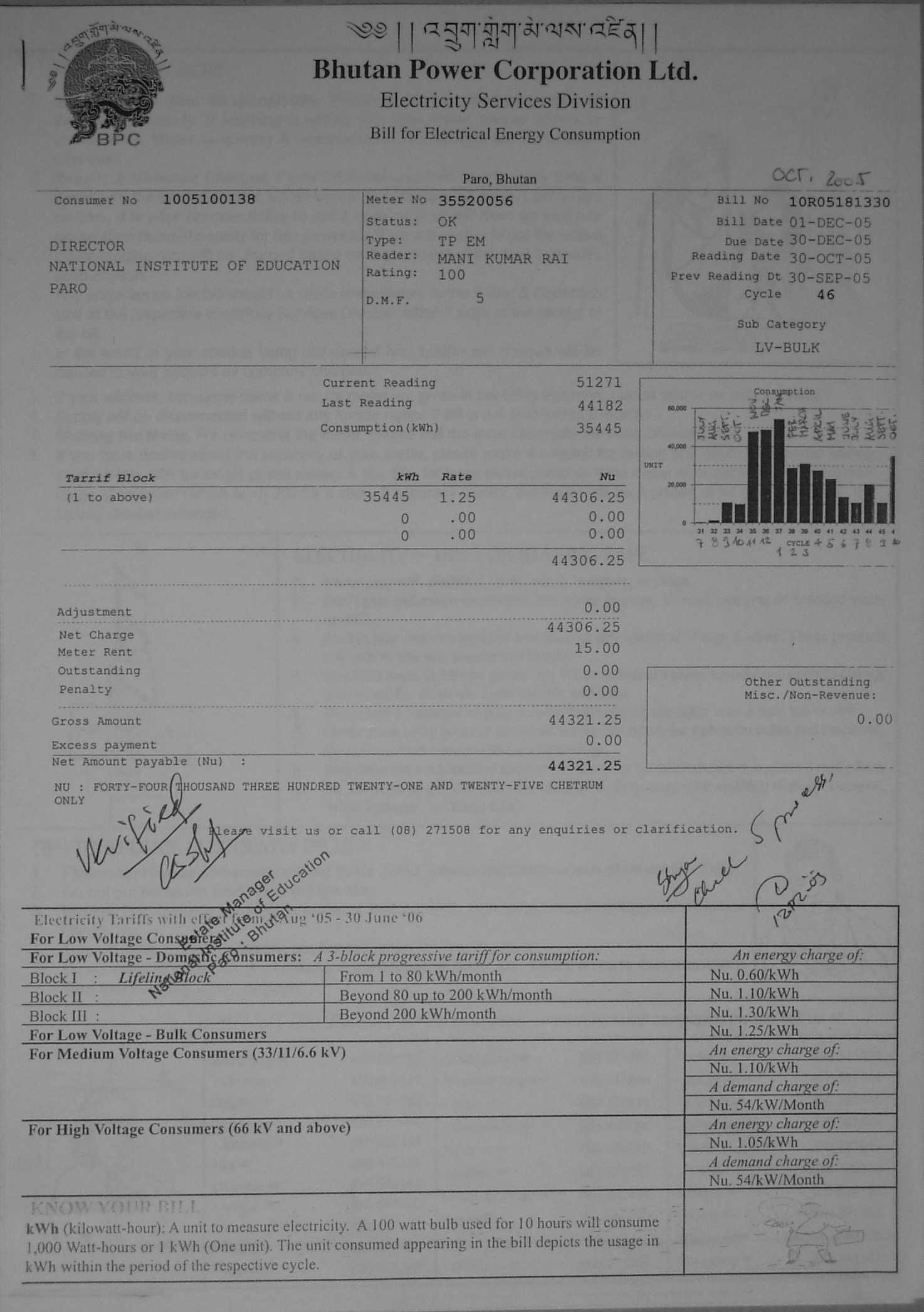
The transformer has a capacity of 1000 kVA which is much more than proposed in the report from 1994. Until now it was not really loaded. With the two new building including heating systems the load will reach a value where the future development has to be observed.
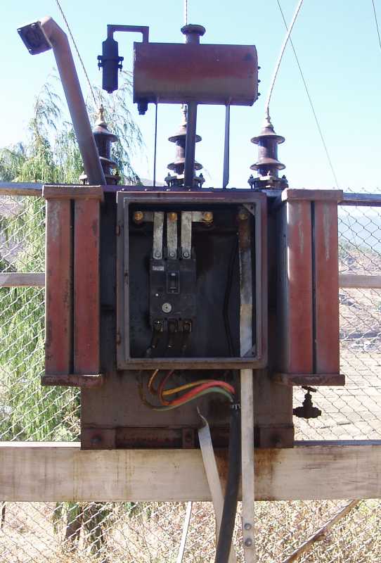
The fence around this transformer station I found always looked with a key which is important for the safety.
 As described in the last report the high tension switch gear is of an astonishing high standard, also referring the level of safety.
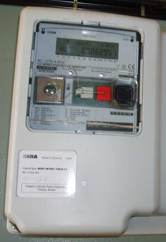 The meter has a memory which memorises the consumed power every quarter of an hour throughout one year. These values can be read out with a single-button menue from the display in an immodest complicated kind. It memorises also a register with the highest values of each month with a timestamp.
The Power Corporation for sure has equipment to read out these values at
once and could
provide it as a table.
The existing L.T. panel is executed to connect heavy load. Out of 6 bays, 2 are used to connect the transformer. The remaining 4 have been occupied already and so it was planned to arrange a new one for the connection of the MDP 2 (heavy load) and the new Visitors Centre (small load). Because there was no free feeder at the existing panel it was even thought to connect the new panel direct form the transformer.
The better solution is to erect a second LT-Panel for smaller outlets and divide he existing connections accordingly. This shall be connected to the existing panel. The location can be chosen according to the length of existing cables to avoid extensions.
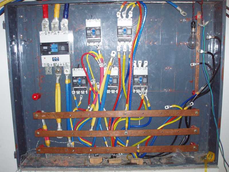
The main MCCB has a nominal value of 630 A. It is set to 0.7 x In = 440 A. The fuses at the T/F station should be larger (630 A), but for a starting period they can be 250 A until the buildings are more utilised and load increases.
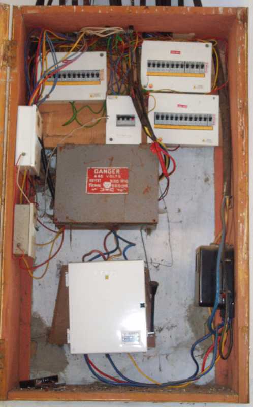
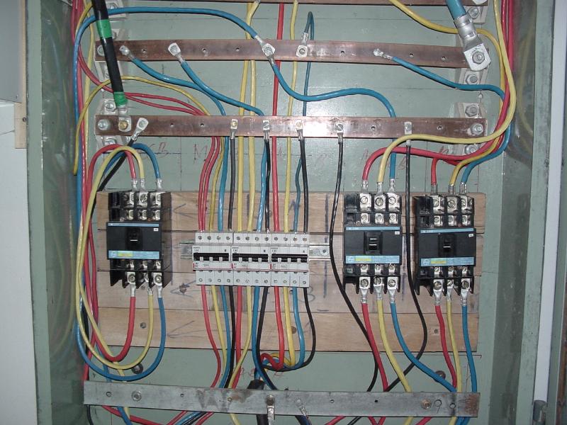
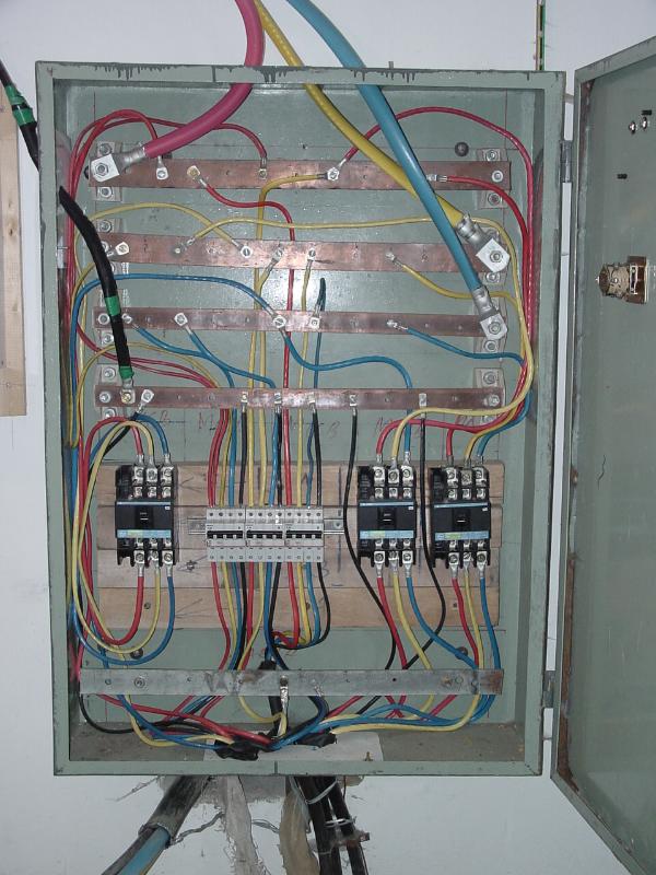
The picture shows the panel at the begin of my inspection. After the compleation all the checks and measurements hav been found ok.
Also here the problem of fixing the MCCBs occurred. It could be solved with wooden planks behind the panel (there was by lucky chance a slot). The MCCBs are fixed with screws through the metal backside into the wood.
Finally the equipment and bars have to be covered with bakelite sheets.
At the very first day of my stay I could avoid a modification at the panels. Because of difficulties fixing the larger equipment inside the panels they changed to fix it with the help of a wooden board inside the panel. This increases the fire load and the risk of fire anyhow because of the highly inflammable material.
In some cases where the panels could be reached from the back, the equipment has been screwed direct through the backside of the panel. In other cases a metal sheet as support was fixed.
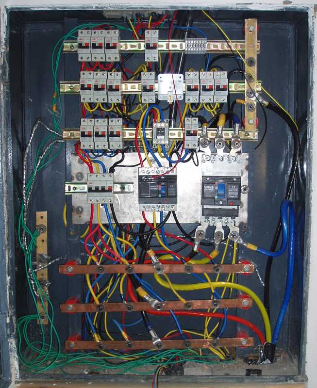
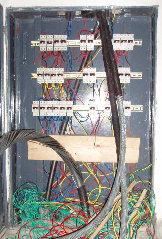
with the wooden support with metal sheet support
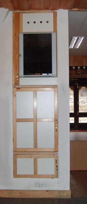
panel at final stage, bakelite sheet removed
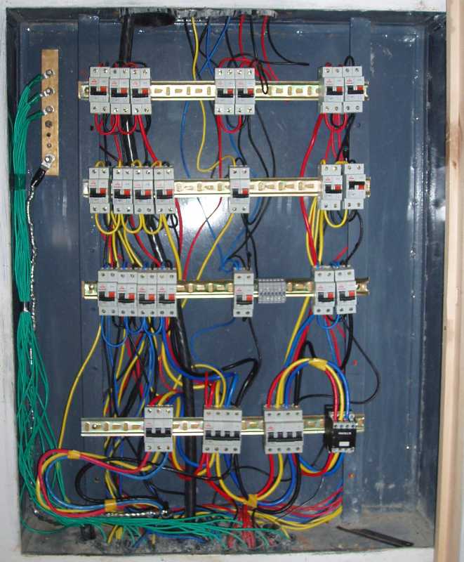
Panels
All the load calculations have a meaning only if they are based on realistic assumptions. And this base is given only when this predictions are verified and improved by measured values.
Load MeasurementMrs. Chimi has done current readings in 2002 and during my stay. According to this measurements the load reaches only approx. 150 kW.
Additionally I could read out some values from the bulk meter. These values are more reliable because they reflect really the peak values and not the values at the time of the reading. Still the manual readings with the clamp-on meter at the outgoing cables are essential to know how much each of the buildings (cables with MCCBs) are charged.
According to the bulk meter the load reaches already 500 kW without the two new buildings. Including the new building it may reach approx. 800 kW.
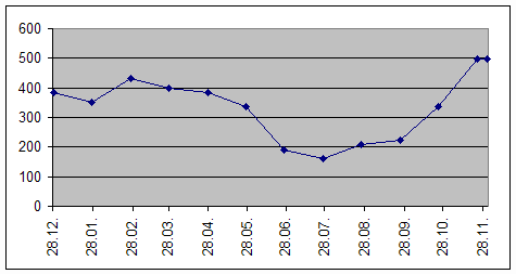
For the Auditorium and the Gym-Hall the load calculation has to be revised. But an estimate was done and this shows that the load will increase approx. 100 kW. It can be assumed that at times where high load is used at these buildings the activities at the other buildings will be low. This means the transformer is still big enough to carry the load after connection of the whole complex. (1000 kVA apparent power of the transformer with a power factor of 0.9 means 900 kW maximum load)
For the connection I early recommended a fix connection without socket / plug to avoid plugging in other appliances. The placement was foreseen beside the heater at the side of the terminal box.

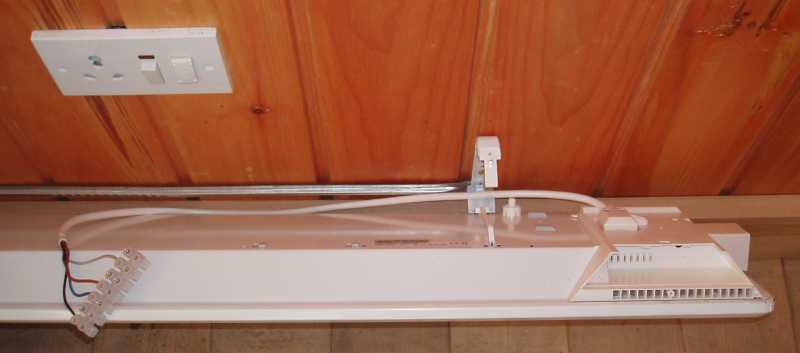 The execution was done with a power socket meant to be hidden behind the heater. But the distance between socket and heater was to small for the plug, therefore the heaters had to be placed below the sockets.
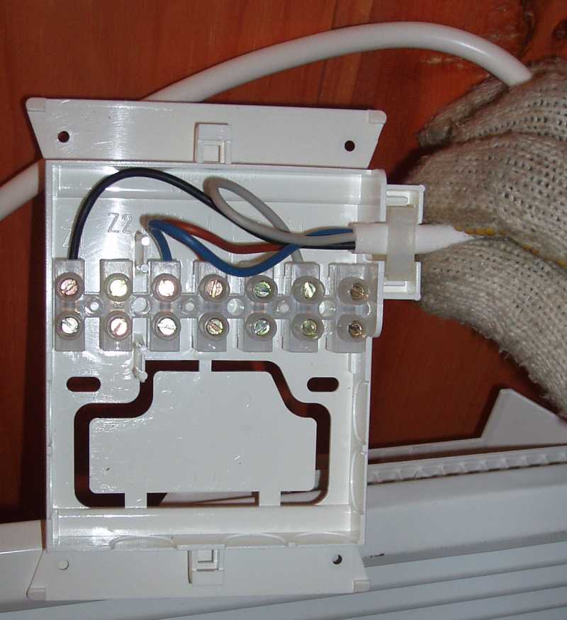
With every heater a connection box was supplied which easily could be mounted surface on top of a conceal box. This had to be removed and a plug installed instead.
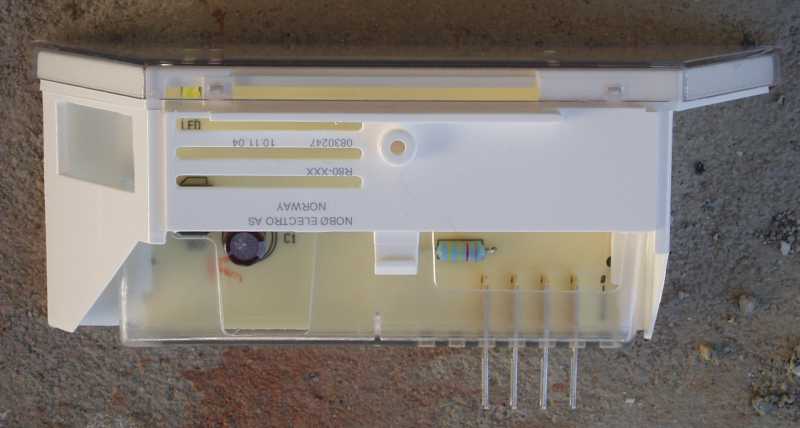
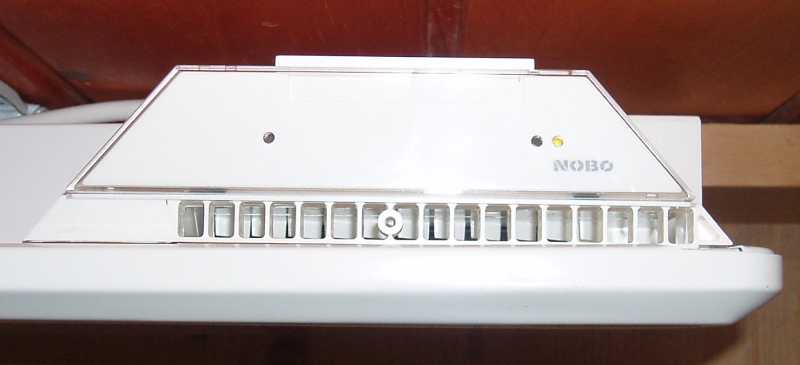 To every heater a 'empty box' has to be inserted to make it run. It indicates with a green LED when running.
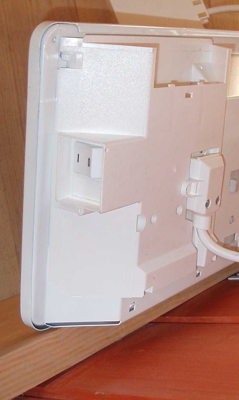
Finally every heater has a built-in switch.
No additional switch would have been needed.
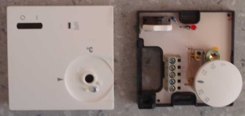 The thermostat is regulating the temperature of a group of heaters. It has to be mounted surface for the reason that the air which is moving in the room by convection does pass by.
The indications (numbers of the terminal connectors) have been different to the description I had from Switzerland. This caused problems while taking the controls into operation.
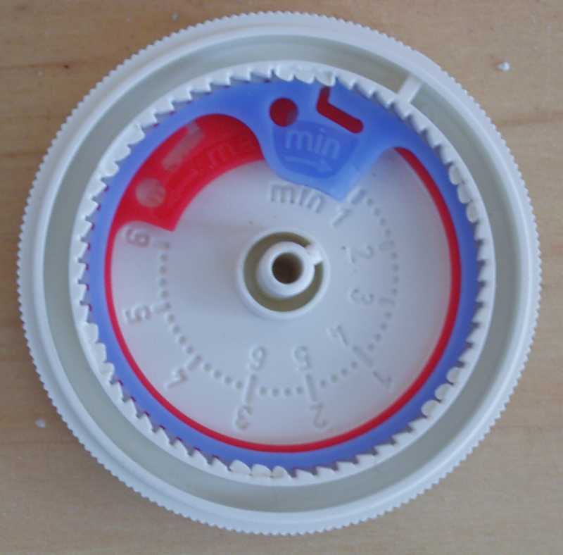
Inside the knob there are to rings. With the help of these rings the range of the temperature wheel can be limited. Specially the maximal value (red ring) should be limited to approx. 22 º C.
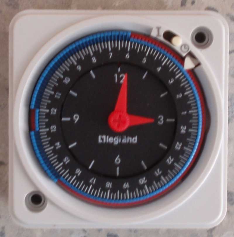
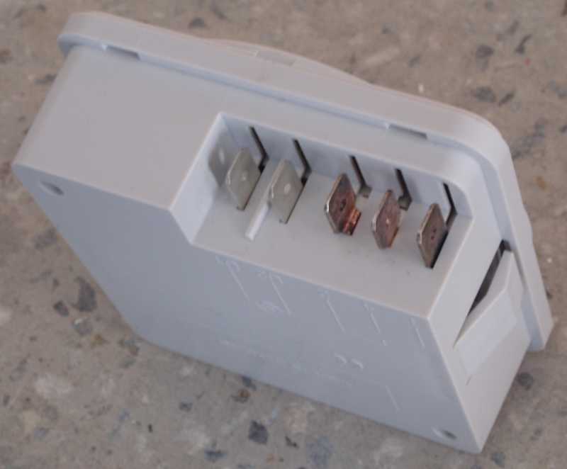 The model of the time switch has been changed somehow. The type used had no screw- terminals but fast-on connectors usually used at automobile electric. For testing we had to twist the wires.
Finally proper connections should be made.
Manuals and connection diagram see at the appendix.
To take into operation the whole heating system at the very last moment caused little bit stress.
Conclusion: Unpacking the materials, testing, making a sample installation at the site office would have solved a lot of problems we had at the last moment.
Manual for heating system
I did not care much about existing (handed over) buildings and their installations. Just when passing by I have seen a few things and made my thoughts. Lack of maintenance has most of the time a direct impact to the safety.
Maintenance Unit (or "Gender Balance")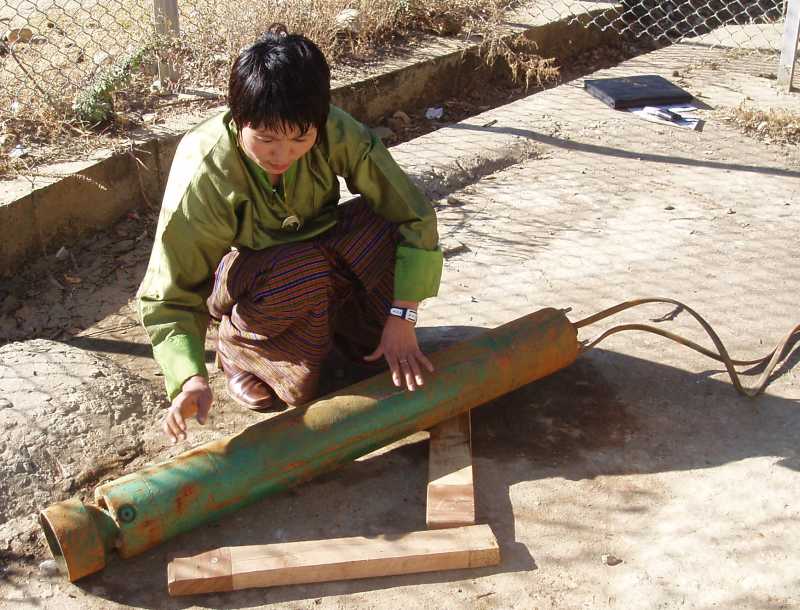 In general the installations are in good conditions.
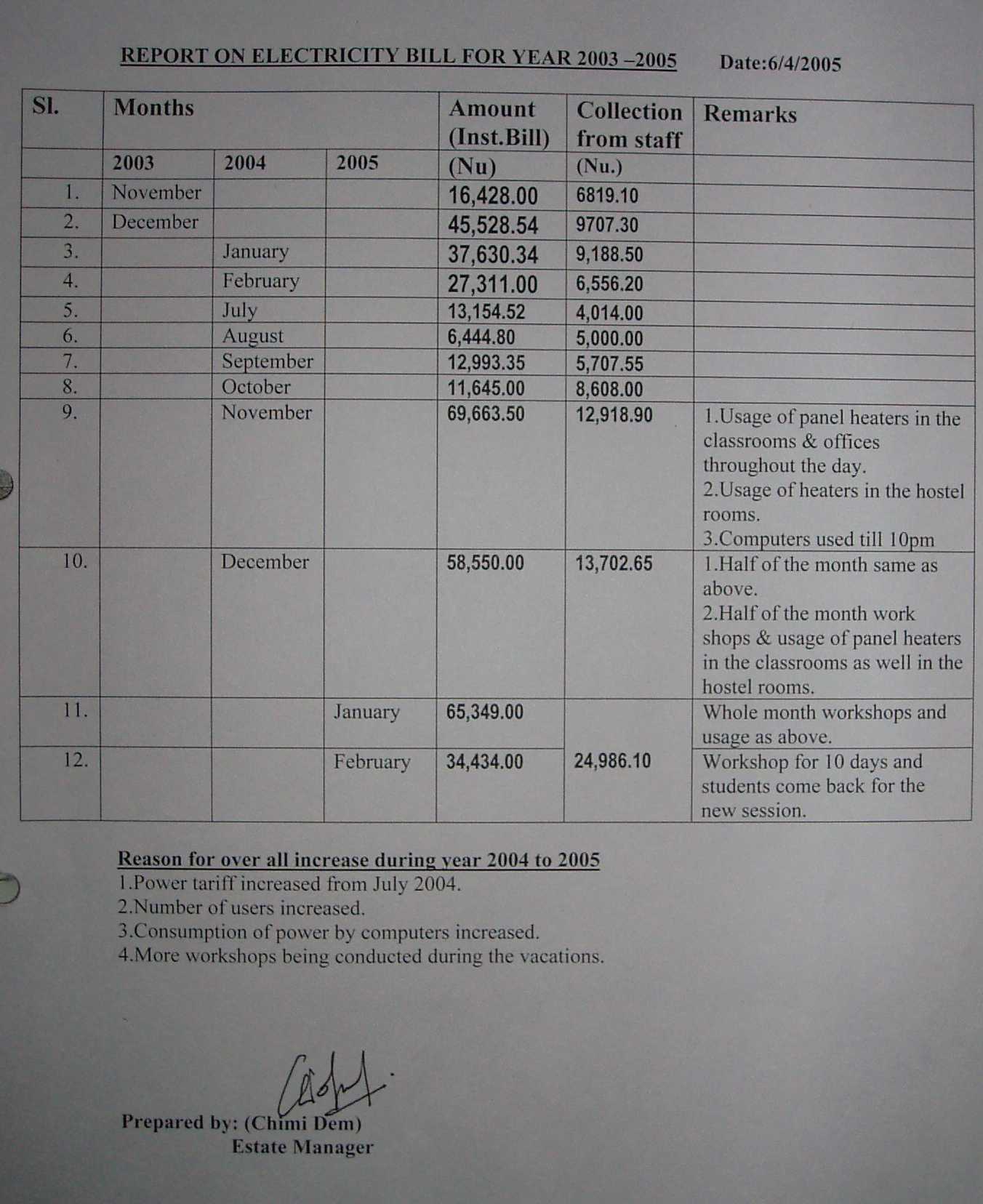
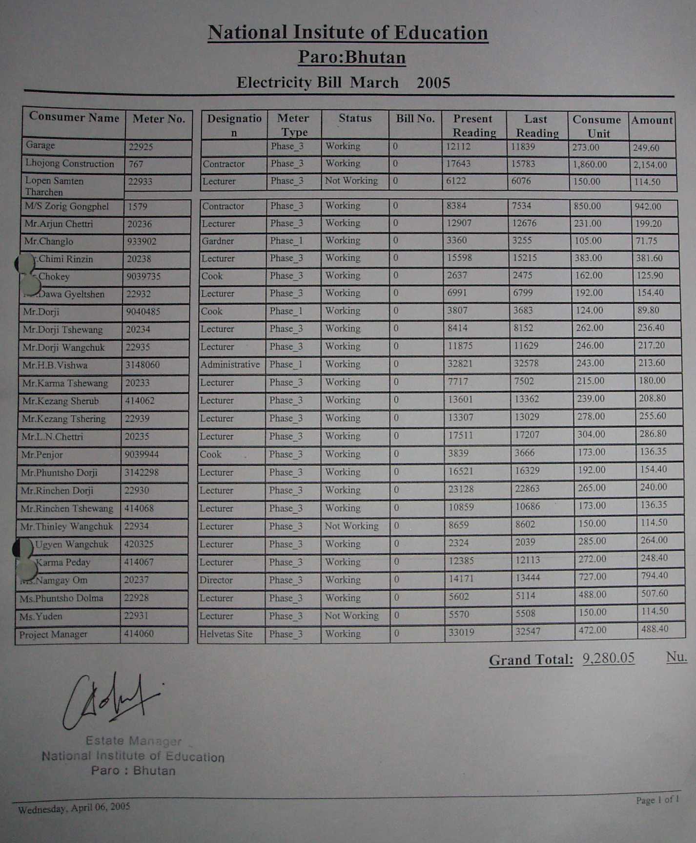
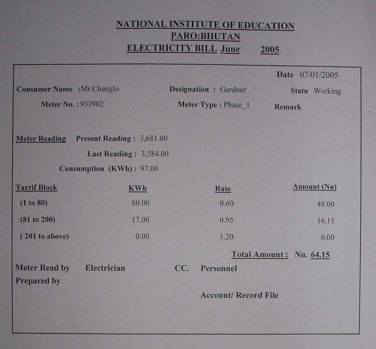
Mrs. Chimi who takes care of the maintenance at the whole school complex does her job well. She does not only the administrative work (calculation and billing of energy consumption of staff quarters, see appendix), she also has shown that she knows to give a hand while dismantling the pump and does not mind to get dirty hands.
Mrs. Chimi is also responsible for the billing of the internal energy consumption of the staff quarters. For this she takes the meter readings monthly and calculates the bills with the help of a XL-sheet.
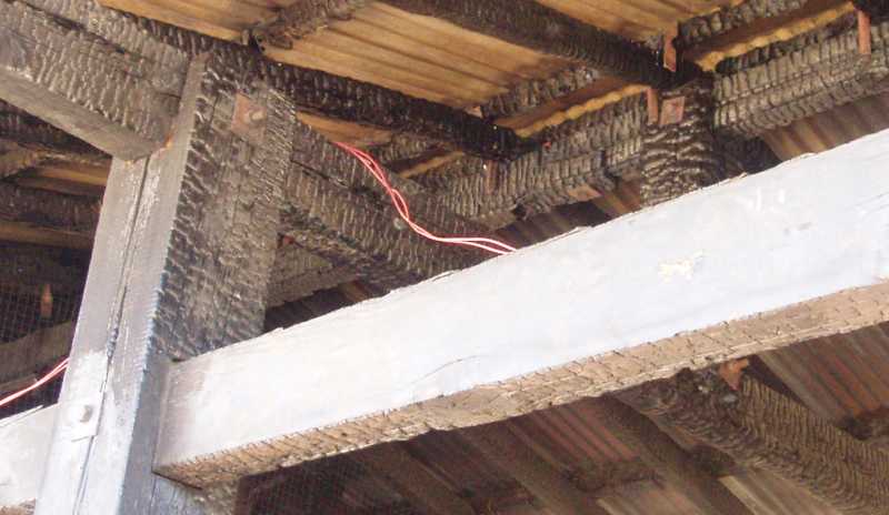 The old kitchen was burnt nearly by an accident and the wiring is destroyed completely. Part of the installation has been put into operation very temporary. Even the roof will not be repaired immediately, the electrical installation should be repaired properly or removed completely (SAFETY).
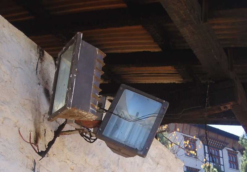
Cooking is moved to a new room and will be done with electrical stoves in future. The installation is done in the local way with clustered MCB-panels at the location and listic wiring. According to the Bhutanese rules and regulations no specific precautions are needed for stoves below 2000 W. In Europe earth leakage circuit-breakers (RCCB, residual current circuit-breaker) are compulsory in kitchens and bathrooms (SAFETY).
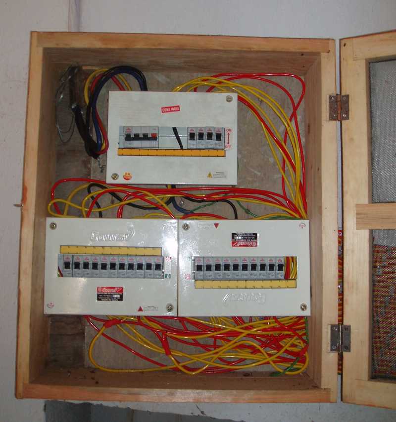
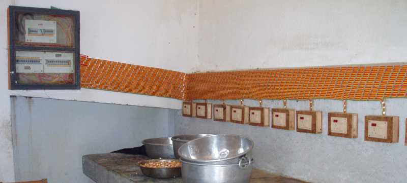
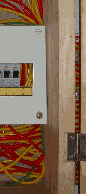
The earth wire (green) is taken only once for all the sockets and is linked from one socket to the other. In Europe this is forbidden because if at one socket the connection is interrupted all the sockets 'behind' have no connection at the earth terminal (SAFETY).
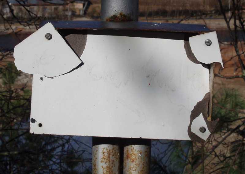
Some bakelite covers of the connection boxes at the illumination poles are damaged. It seems that vandalism starts to take place at the school.
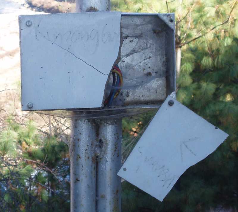
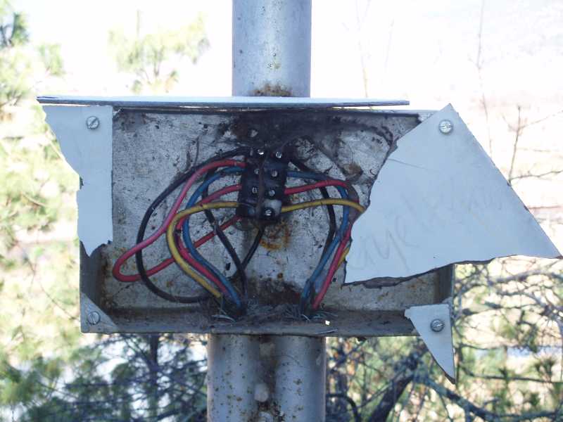
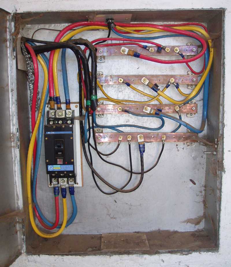 This Panel (SDP 13) which is directly accessible from outside and which is in a height where even playing children may reach it is not locked and the naked copper bus-bars are not covered with bakelite sheet. In my opinion access should only be given to the wardens even for smaller MCBs, because tripping of MCBs points to problems.
Tripping of such a device (MCCB 200 A) is always caused by a serious problem which should be followed up and not switched on by anybody.
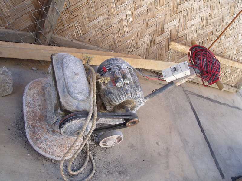
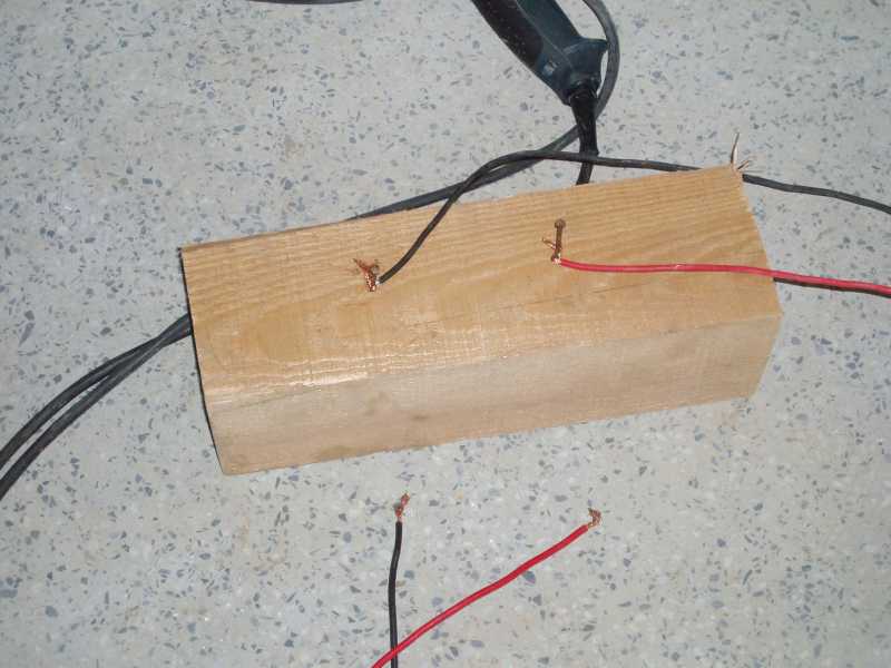
No direct influence can be taken to the safety at the site during construction. A few pictures shall illustrate to poor level of safety measures.
Distribution point for electricity Grinding machine with extension cable and open belts
In general still the TT-System is applied with single earth points and this points connected with a thin wire to the earth-pins or to the bodies.
Main-cables are carried out in 3 ½ core that means even Neutral is reduced to the half cross section area. The steel-armour of the cable which is mainly a mechanical protection is used for the earth. Sometimes it is not connected because due to leakage current they fear a burning of the cable. At the supply point the earth wires are connected to a weak earth-plate which has a high resistance. This leads in case of leakage current (what is often the case) to a high voltage drop and finally to a voltage at the Neutral up to 50 Volts.
At the NIE for the earthing the reinforcement of the concrete is used. The measured values have been ok. Due to leakage current via the earth at the transformer station there is a potential difference between earth (ground) an the Neutral. That means Neutral is not "neutral" anymore and has a voltage of approx. 30 volts against the earth. This is not dangerous and quite common but looks little bit strange. It could be improved while applying the TN-System. (see my report from 1999, page 24 chapter 10.8 Connection between Neutral and Earth)
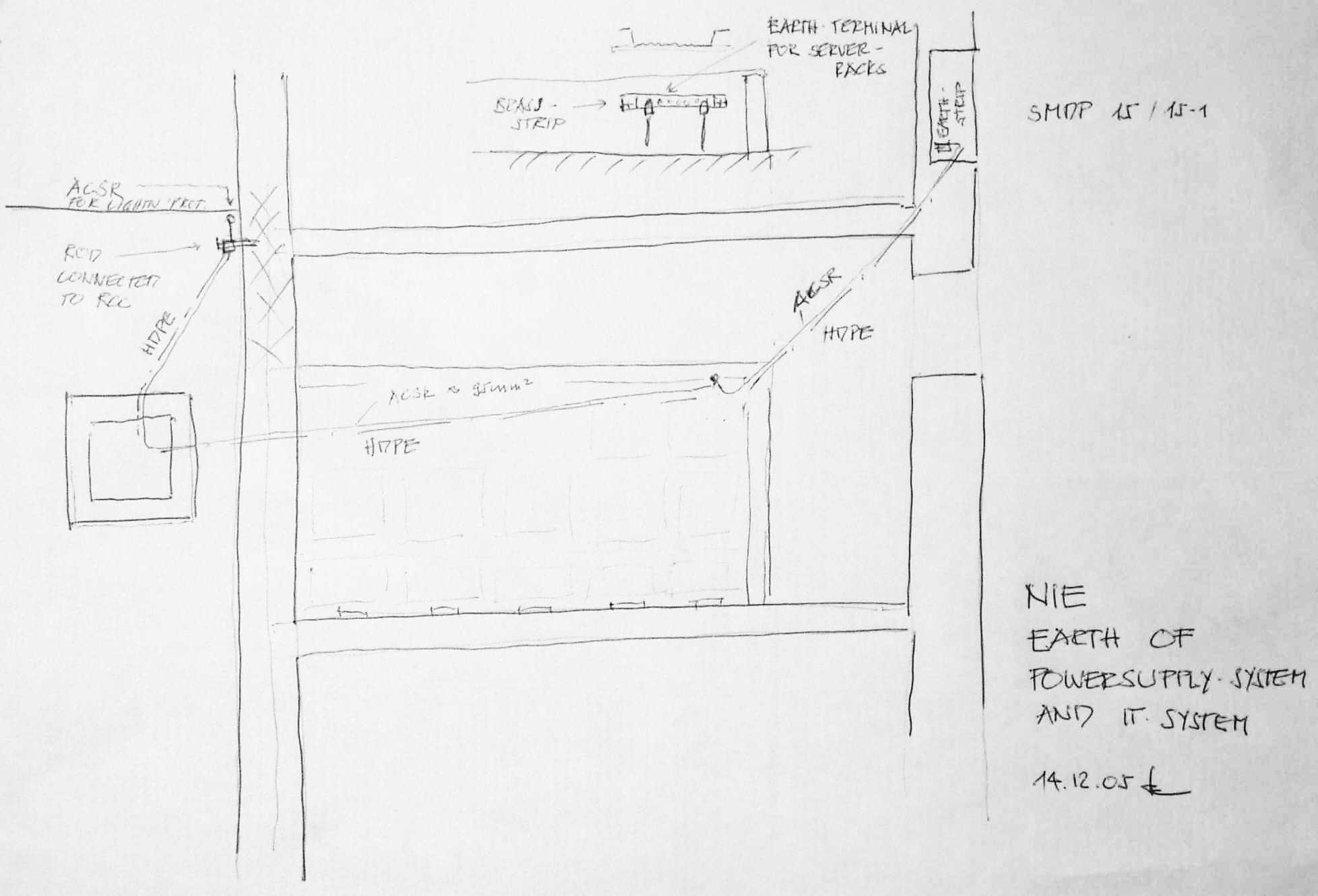 At the Computer Centre the earth had to be taken from a connection point outside (same point as lightning protection). This earth-wire passes by the server room where a provision was made to connect the server-racks.
The water pump does not work and has electrical leakage on the water pipe system (line tester is glowing).
SurveyOn 6.12. the water pump has been checked the first time. The earlier pump inside the pump house was removed. The controls have been found in good conditions.
meter, main switch controls from the old pump new control panel
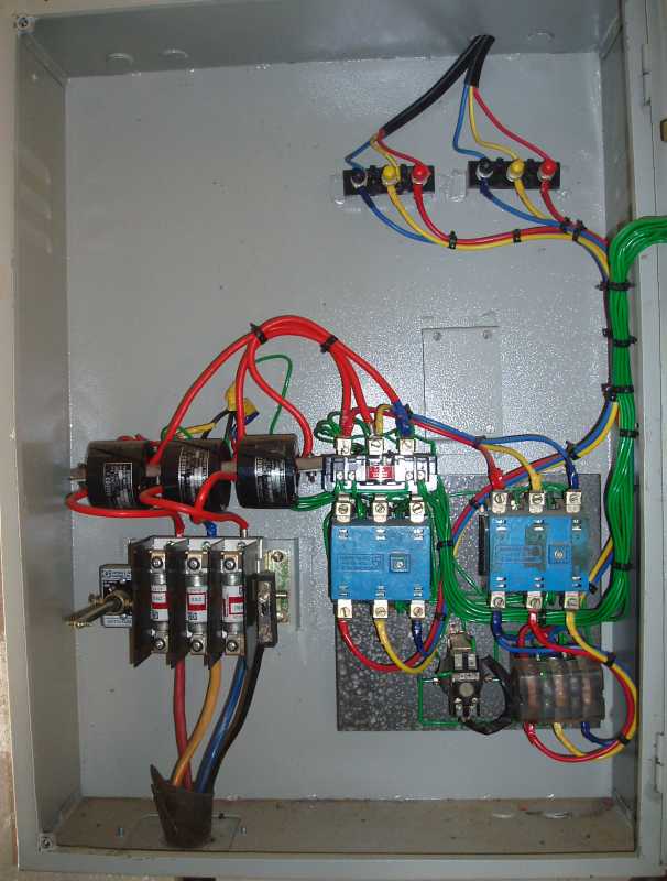
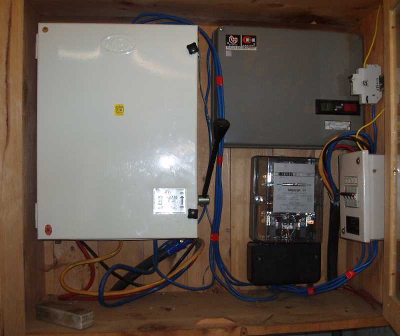
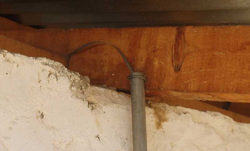
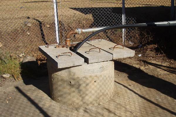 The measuring of resistances and of the insulation showed a broken connection as well as a leakage in one phase. Because we could not reach the pump it was not clear whether the fault was in the cable or at the pump. Both the cables had a taping approx. 1 m below the concrete plates. This is normally above the water level but rain drops could flow along the cable and enter the taping.
It was decided to lift the pump and to dismantle it.
After lifting the pump we started to dismantle on 14.12. The taping at the cables we found ok. The pump we could divert from the motor but could not open the motor itself. For repair it has to be brought back to the supplier.
The old motor - pump - set was replaced with an underwater well-pump. The reason was that the existing pump had problems to suck the water.
From the point of maintenance the old set was the better solution because any standard motor can be fixed with a flange to the pump.
In case the water catchment is enlarged and the inflow is improved it would be fine to install a second pump on the old base. This would increase also the availability due to redundancy in case of malfunction of a pump.
I was asked to make some comments to the handed over proposal for a diesel generator set from the technical point of view.
The proposal which is in fact a offer including the prices and financial conditions is comprising a complete and functioning emergency generating set.
Diesel engine (PERKINS) as well as the generator (F. G. WILSON) are produced in UK and both brands are well known and installed at many places in Europe.
Size:
One set has a nominal capacity of 500 kVA, that means 400 kW at power factor 0.8.
Today's maximum load is already about 500 kW and with the to new buildings approx. 270 kW will be added. Either a two generator set should be procured or load management has to be organised that means the set can not start automatically.
The integration to the existing distribution system seams to be thought over well. A additional board is offered which has not to be placed near the engine but can be placed at the main supply point.
Care should be taken to interfaces as exhaust pipe, tank, store for additional fuel.
(commercial conditions, need: quit a expensive solution to solve a "minor" problem, thinking of running costs for frequent service)
This installations are not part of my contract.
In February 2003 I made some recommendations how to distribute the network cables and this was followed more or less (see appendix).
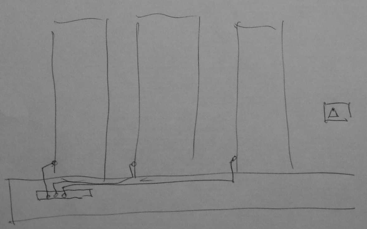 The interfaces (supply for hubs and earth system) had been discussed with Mr. Chris Hartmann.
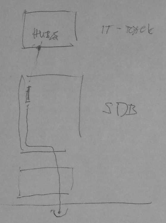
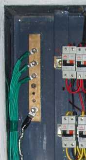
Since a few years there are existing Bhutanese "Specifications for Electrical Works (Internal) from the Standard & Quality Control Division.
As far as I could see the "Helvetas-standard" does not infringe these standards.
This standards should be studied carefully. In cases where the "Helvetas-standard" is higher we should furthermore stick to this level. It is always allowed to do more for the safety than the minimum requirements but the Bhutanese rules should not be violated.
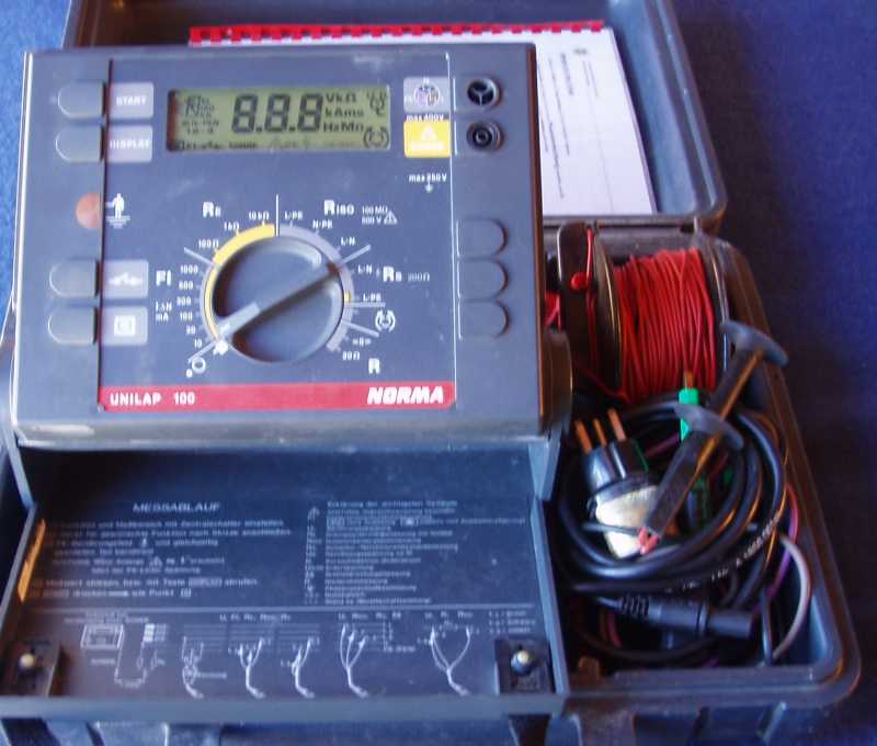 For the testing a ... meter has been used. This allows to carry out different meter readings with the same meter. But most of the checks have to be made only once before taking the installation into operation.
For the usual maintenance work Mrs. Jhimi is equiped with sufficient meters (universal meter, megger, clamp-on-meter)
For checking the proper connection of the power sockets 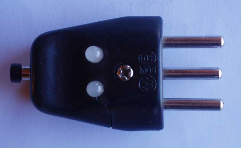 we use in Switzerland an "easy-check-plug" which indicates right connections with green LEDs and wrong connections with red LEDs. This plug can be used together with a adapter also for Indian sockets. This allows a fast and efficient checking of the sockets. I left this plug with the maintenance crew to finalise all the checking of the sockets.
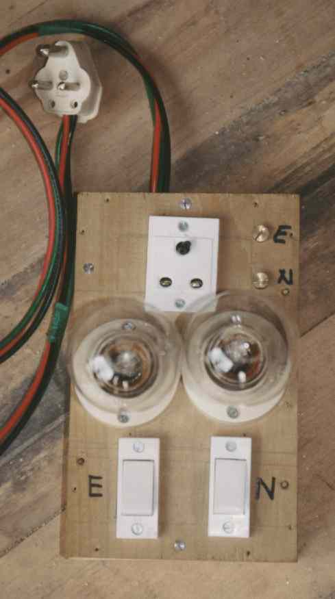 Instead of such a plug a self made box like described in my last report (page 30, chapter 10.10 Checking of Wiring) can be used in the same way.
During my stay in Thimphu at the architects office I checked the electrical part of the tendering documents. Special attention was given to the diagrams of the distribution boxes an the dimensioning of cables and MCBs / MCCBs.
The connection of the buildings to the existing distribution system is clarified.
The illumination mainly of the high and large rooms has been recalculated with a XL-calculation sheet which can be used for future calculation.
The installation at the Rinpung compound has been check. It is in a poor condition and has to be removed a built again.
Main panel with meter Bus-bar box
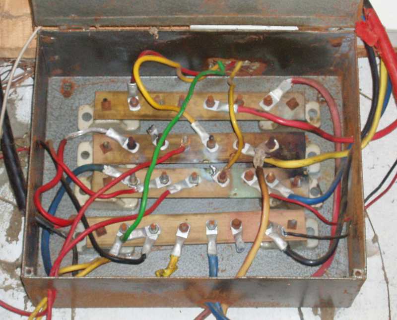
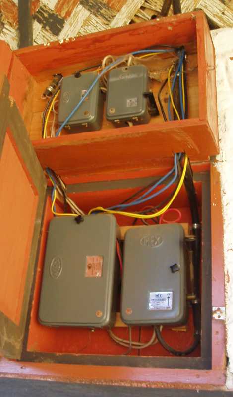
Following solutions have been discussed:
Appendix Action Plan
General remarks
|
Object |
Description |
Action |
Remarks |
|
Bakelite Sheets |
to protect |
on all panels |
|
|
Checking the functionality of switches, light points |
according to layouts |
all circuits |
|
|
Checking of proper connection of the power sockets |
according to instruction |
all power sockets |
|
Particular remarks
|
Object |
Description |
Action |
Remarks |
|
T/F-Station |
connection of new buildings |
arrangement of new D.B. 2 according to drawing |
|
|
OB, Earth |
connection from RCC- Rod |
||
|
OB, Earth improvement |
additional connections to the earth |
links at all SMDB's from RCC to the earth terminal |
|
|
CC, Earth |
carry out according to drawing |
||
|
CC, Earth improvement |
additional connections to the earth |
links at all SMDB's from RCC to the earth terminal |
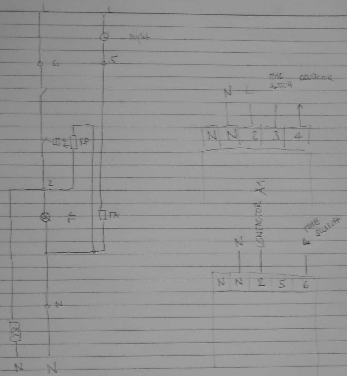
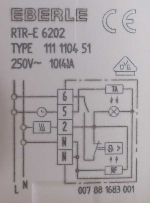 given diagram connection to panel
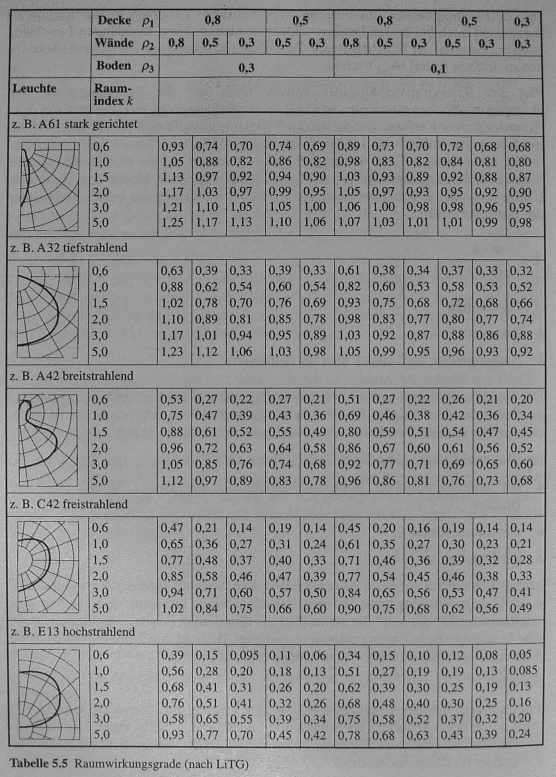 Table for Raumwirkungsgrade according to Lichttechnische Gesellschaft
Processing on 13.01.2003
Von: Fritz Baumgartner [[email protected]]
Gesendet: Montag, 13. Januar 2003 04:46
An: Steiner Hans TB Rorschach
Cc: Werner Christen; NIEBH22
Betreff: Photos MDP
Lieber Hans
Im Anhang sende ich Dir Photos des Main Distribution Panels welches im SB4 im Keller steht. Es ist kaum moeglich im Panel die Anschluesse fuer die neue Phase zu machen oder was denkst Du?
Bis bald
Fritz Baumgartner
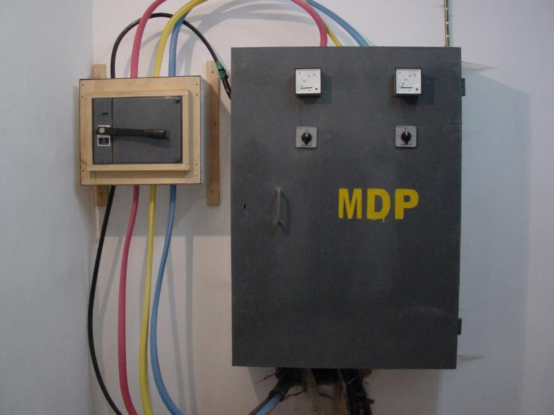
NIE_MDP in SB4 BM_1.jpg
NIE_MDP in SB4 BM_3.jpg
NIE_MDP in SB4 BM_2.jpg
kritische Bemerkungen zu bestehendem Panel:
1. kein Schutz an Kanten
2. mehrere Abgänge unter 1 Schraube
3. falsche Drahtfarbe
4. Abgänge 1x oben, übrige unten
-> Anschluss der neuen Gebäude nicht an dieses Panel
Processing on February 2003
Schwachstrom-Verkabelung
1. Grundsätzliches
Bisher habe ich mich noch nie um die Schwachstromverkabelung (Telefonie) gekümmert, habe aber festgestellt, dass bei den mehr oder weniger zufällig inspizierten Installationen einiges an Verbesserungspotential vorhanden ist.
In der Schweiz wird in Bürogebäuden heute mehrheitlich die universelle Gebäudeverkabelung angewendet. Diese braucht nicht mehr Kabel, ist (hier) nicht teurer und ist auch nicht komplizierter zu installieren oder zu verstehen als eine konventionelle Verkabelung.
Es ist zu beachten, dass eine konventionelle (getrennte) Telefonie- und Netzwerkverkabelung auch je Unterverteilungen benötigt, damit die entsprechenden Telefonnummern und PC-Arbeitsplätze zugeschaltet werden können. Günstiger wird es nur, wenn die Telefoniedrähte weiterhin nach Bhutan-Standard irgendwo zusammengedreht werden und nur für die Netzwerkverkabelung ein sauberer Aufbau gemacht wird. Ansonsten wird die universelle Verkabelung günstiger, da das gleiche Material verwendet werden kann und die Reserve nicht für beide Medien separat vorgesehen werden muss.
"Wireless" für die Netzwerkverkabelung rate ich im Moment ab. Bis zu den einzelnen Räumen (allenfalls Stockwerken) muss trotzdem eine saubere Installation erfolgen, dazu kommen die Sender / Empfänger, die bei uns die Installation gegenüber Draht-gebundener Installation wesentlich teurer machen. Bei uns wird der Vorteil nicht im Preis gesucht, sondern in der Ästhetik.
Das Material für die universelle Verkabelung wird bei uns in derartigen Mengen gebraucht und ist derart "Standard", dass ich mir nicht vorstellen kann, dass es bei euch nicht verfügbar sein sollte.
Aus diesen Gründen empfehle ich für eine Schule mit noch unbestimmten, tendenziell aber wachsenden IT-Bedürfnissen, die universelle Gebäudeverkabelung anzuwenden. Für bestimmte Räume kann eine andere Strategie Sinn machen. So ist es sinnvoller, in PC-Schulungsräumen direkt einen Switch für die benötigten PC’s zu installieren.
2. Prinzipieller Aufbau
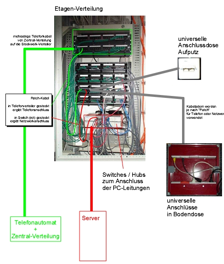
An zentralen Stellen werden Verteiler installiert (pro Stockwerk, pro Sektor). Diese Verteilkasten sind in 3 Bereiche unterteilt:
Somit kann nun jeder Steckplatz bei den Arbeitsplätzen mit einem Patchkabel wahlweise auf den Telefonverteiler oder auf den Switch verbunden werden. Werden bei einem Arbeitsplatz 3 Anschlüsse zur Verfügung gestellt und ist je einer für Telefon und PC belegt, so kann der Reserveanschluss bei Bedarf für einen Telefon oder für einen PC verwendet werden.
Die beiliegende pdf-Datei zeigt einen Etagenverteiler bei den Technischen Betrieben Rorschach. Die Patch-Kabel müssen nicht verschiedenfarbig sein, dies dient nur der Übersichtlichkeit (grün sind Telefonanschüsse, rot sind wichtige Anschüsse (Server, Switch-Switch, blau sind Verbindungen über Stockwerke, grau die PC-Arbeitsplätze).
Schwenkrahmen für die Racks sind nicht notwendig; der installationsseitige Anschluss hinten ist nur einmal zu machen und kann auch von vorne erfolgen.
3. Spezifikationen
3.1 Stecker / Buchsen
Für sämtliche Verbindungen werden die selben Stecker und Buchsen verwendet.
Typ: RJ45, 8 polig
Dies sind die selben Typen die auf den Netzwerkkarten der PC’s standardmässig verfügbar sind. Auf den Verteilern wie bei den Switches sind alles Buchsen, die Patchkabel haben 2 Stecker. Ebenso haben die Anschussdosen wie auch die Netzwerkkarten Buchsen, d.h. für den Anschluss an den Arbeitsplätzen werden "längere Patch-Kabel" mit 2 Steckern verwendet.
Für den Anschluss von Telefonapparaten sind heute bei Analog-Apparaten RJ15-Stecker, bei ISDN-Apparaten RJ 45 Stecker üblich. Die RJ15-Stecker können auch in RJ45-Buchsen gesteckt werden und bei richtiger Adernbelegung funktioniert diese Verbindung zuverlässig.
3.2 Kabel
Für Netzwerke wird heute im Bürobereich 100 Mbit/s verwendet. Dazu genügen Kabel mit verdrillten Adern ohne Abschirmung der Kategorie 5.
Typ: UTP Cat. 5 (unshielded twisted pair)
Der Anschluss auf die Stecker erfolgt 8 polig, wobei für Telefon und PC nur 4 Adern benötigt werden. Hier wäre noch ein Sparpotential.
4. Anschlüsse
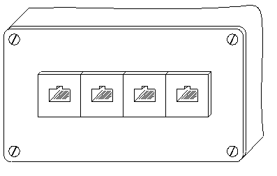 Der Anschluss an Dosen / Stecker erfolgt mit Crimp-Zangen und ist für nicht Farbenblinde einfach und zuverlässig zu erstellen (ohne zu löten, keine Twists).
Die Buchsen werden von vorne mit einer Schnapp-Befestigung in eine Öffnung gepresst. Für einen Arbeitsplatz-Anschluss kann eine Montage wie bisher bei den Starkstrom-Steckdosen (Holzdose und Bakelite-Sheet – Abdeckung mit conceal-Steckdose) angewendet werden.
5. Platzbedarf Verteiler
Auf einem 19"-Rack können bis 24 Buchsen in einer Linie untergebracht werden. Bei unserm Betriebsgebäude ist diese Verteilung in der Steigzone unter der Starkstrom-Verteilung untergebracht (ca. 1 m hoch). Die Tiefe wird im wesentlichen durch die Switches bestimmt. Die Verteilleisten sind nur ca. 15 cm tief, für Switches werden üblicherweise min. 30 cm benötigt.
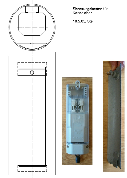 Processing on 10.5.05
Von: Fritz Baumgartner [[email protected]]
Gesendet: Dienstag, 10. Mai 2005 04:46
An: Steiner Hans
Betreff: Detail
Lieber Hans
... Du kennst sicher die Oeffnung fuer die Verkabelung in den Strassenlampen. Auf einer Hoehe von 1m hat es oft einen Deckel den man mit einem Vierkantschluessel oeffnen kann. Habt Ihr eine Zeichnung wie das gemacht ist oder hast Du eine Photo vom Innenlebel? Wer verkauft bei Euch diese Lampenrohre? Ich koennte sonst vielleicht auf deren Homepage sehen. Hier machen sie meistens eine Blechkiste an den Kandelaber und nachdem der Deckel jeweils abfaellt sind alle Kabel offen! Ich habe eine Zeichnung gemacht, aber meine Blechbieger und Schweisser koennen das Detail nicht richtig umsetzen.
... Fritz Baumgartner
-----Original Message-----
From: Steiner Hans
Sent: Tuesday, May 10, 2005 1:12 PM
To: 'Fritz Baumgartner'
Subject: Detailangaben Kandelaber
Hoi Fritz
Ich habe dir eine Skizze mit Fotos gemacht.
Die Kandelaber beziehen wir von Kolb Protech in Oberriet, der hat keine Homepage (nur echte Hardware).
Früher von
http://www.rutschmann-ag.ch/d_index.html, der produziert aber nur noch Kandelaberfundamente.Der Deckel ist wahrscheinlich mit Laserbrenner geschnitten, damit er sauber passt (konische Kandelaber), aber bei einem abgestuften Kandelaber kannst du Deckel auch aus einem Rohrstück sägen. Der Deckel ist bündig und liegt oben und unten etwa 2 mm auf.
Unten eine 'Nase'zum Einhängen, oben eine Schraube, die in einem zylindrischen Loch versenkt ist. Dieses liegt dann auf dem Steg im Kandelaber auf, der ein Gewindeloch oder eine aufgeschweisste Mutter hat.
Ältere Modelle liegen aussen auf und haben oben ein 'Regendächli'.
Im Kandelaber innen ist in der Längsrichtung ein C-Profil Stahl eingeschweisst. Darauf werden mit Schlittenmuttern vorgefertigte 'Sicherungs-Kistli' montiert. Diese beziehen wir von
www.visiolux.ch, sind aber auf der Homepage auch nur Referenzen, keine Masszeichnungen.Das Kistli beinhaltet Sicherungen. Wenn du das Kabel, das von Kandelaber zu Kandelaber geht mit 25 A absicherst (z. B 6 mm²), dann kannst du im Kistli eine 10 A (oder 6 A) Sicherung einbauen und ab Sicherung hinauf bis zur Lampe mit 1.5 mm² fahren.
Viel Spass beim nachbauen.
Gruss Hans
Processing on 13.9.05
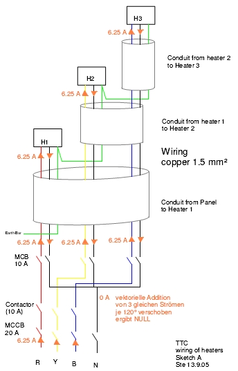
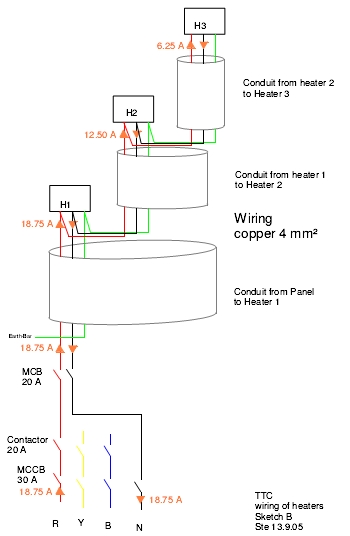
Heaters should be connected with 3phase wiring to reduce the current!
Sketch A: 3phase wiring Sketch B: 1phase wiring
